5  Graph Theory and Causal Patterns

Status: Draft

v0.4

5.1 Introduction

This chapter establishes graph theory as the foundation of the Structural layer: how we represent causal structure as a directed graph. We build from the dyad (Chapter 2) to complex graph structures, showing how much causal reasoning can be reduced to properties of paths and conditioning sets.

NotePackages implement the examples

This book’s framing is general: structure, dynamics, and observation for complex dynamical systems. Executable examples use a Julia stack, CausalDynamics.jl (identify), CausalTargeted.jl (estimate LMTP / mediation), DAGMakie.jl (display). The book is not package documentation; manuals and changelogs live in the repositories.

Code keeps standard Pearl / targeted-learning names (Intervention, do_surgery, backdoor_adjustment_set, run_lmtp_grid, …). Prose may use a sparse process gloss where it helps: prehension (taking account of), shared \(U\) as creative advance (Introduction), L3 alternative concrescences, and Chapter 9’s organism / environment / Markov blanket / society vocabulary for CDM scope (\(\mu\), \(\eta\), \(s\), \(a\), \(G\), \(F\)). Prefer ordinary words (observation, intervention, time step) elsewhere. Mapping: Concept Reference, Tables 4 and 8.

Package source as notation. Where the implementation is the explanation (graph surgery, path blocking, shared-\(U\) counterfactuals), chapters may show a short, syntax-highlighted excerpt from the owned packages in a “From …jl” callout, alongside executed API chunks. Those excerpts are curated under snippets/package-source/; they are not a substitute for the Documenter manuals.

Key principle: All complex structures are combinations of dyads. The graph structure \(G = (V, E)\) is composed entirely of dyads (two nodes connected by one directed edge). Complex causal structures emerge from how dyads connect and overlap.

5.2 Graph Theory and Directed Dependencies

5.2.1 Building from Dyads

As established in The Primary Unit: The Dyad, a dyad consists of two nodes connected by a single directed edge: \(X \rightarrow Y\). This is the minimal unit of directed dependence in a causal graph.

Key principles:

  • One dyad = one directed dependence
  • The dyad encodes a local mechanism, typically written as \(Y \coloneqq f(X, U)\)
  • Complex structures are combinations of dyads
  • Graph structure = collection of dyads (two nodes, one edge each)

5.2.2 Graphs as Structural Structure

In a structural causal model, we have \(\mathcal{M} = (G, U, F, P(U))\) where \(G\) is a directed acyclic graph (DAG) representing causal structure (Pearl 2009; Spirtes et al. 2000). Formally, a graph is defined as \(G = (V, E)\) where:

  • \(V\) is the set of vertices (nodes / variables)
  • \(E\) is the set of edges (directed pairs) encoding direct dependencies assumed by the model

Each edge in \(E\) represents a dyad. The graph structure emerges from how these dyads connect.

5.2.3 Why Directed Acyclic Graphs?

DAGs are natural in many causal problems because:

  1. Direction: causal influence is directional. An edge \(A \rightarrow B\) means \(A\) is a parent of \(B\).
  2. Acyclicity: acyclicity rules out directed feedback within the structural graph (useful for many identification results).
  3. Parent sets: the parent set \(\text{Pa}(X_i)\) lists the direct inputs to the mechanism for \(X_i\).

5.2.4 The Three Fundamental Causal Patterns

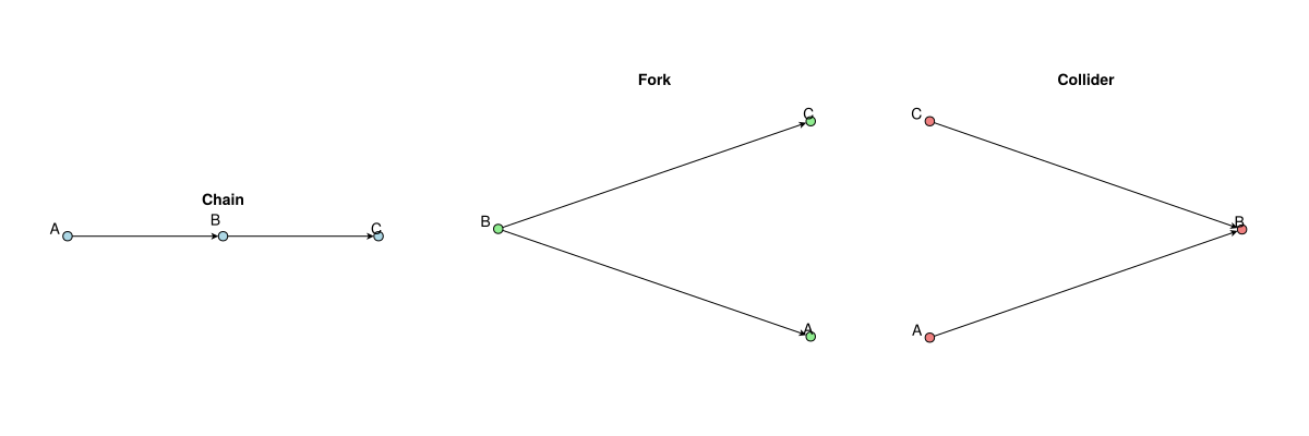
The three fundamental patterns in causal graphs are all combinations of two dyads:

5.2.4.1 Chain: Two Sequential Dyads

Pattern: \(A \rightarrow B \rightarrow C\) (two sequential dyads)

  • Dyad 1: \(A \rightarrow B\)
  • Dyad 2: \(B \rightarrow C\)

Meaning: A mediating chain. This creates a directed path of influence.

d-separation: \(A\) and \(C\) are dependent marginally, but independent conditional on \(B\) (the mediator blocks the path).

5.2.5 Implementation: Visualising the Three Fundamental Patterns

We can visualise and verify the three fundamental patterns using Graphs.jl and GraphMakie:

# Find project root and include ensure_packages.jl
project_root = let
    current = pwd()
    while !isfile(joinpath(current, "Project.toml")) && !isfile(joinpath(current, "_quarto.yml"))
        parent = dirname(current)
        parent == current && break
        current = parent
    end
    current
end
include(joinpath(dirname(Base.active_project()), "scripts", "book_bootstrap.jl"))
@auto_using DAGMakie CairoMakie Graphs

# Pattern 1: Chain A → B → C
g_chain = SimpleDiGraph(3)
add_edge!(g_chain, 1, 2)  # A → B
add_edge!(g_chain, 2, 3)  # B → C

# Pattern 2: Fork A ← B → C
g_fork = SimpleDiGraph(3)
add_edge!(g_fork, 2, 1)  # B → A
add_edge!(g_fork, 2, 3)  # B → C

# Pattern 3: Collider A → B ← C
g_collider = SimpleDiGraph(3)
add_edge!(g_collider, 1, 2)  # A → B
add_edge!(g_collider, 3, 2)  # C → B

# Visualise all three patterns
let
    # Taller figure so DataAspect panels have room for node markers on flat chains
    fig = Figure(size = (1200, 480))
    ax1 = Axis(fig[1, 1], title = "Chain")
    ax2 = Axis(fig[1, 2], title = "Fork")
    ax3 = Axis(fig[1, 3], title = "Collider")

    dag_kw = (
        layout_mode = :acyclic,
        node_color = RGBf(0.30, 0.55, 0.70),
        node_size = 34,
        edge_width = 2.0,
        arrow_size = 14,
        nlabels_fontsize = 16,
        nlabels_color = :white,
        nlabels_align = (:center, :center),
        nlabels_distance = 0,
        auto_align_labels = false,
        padding = 0.35,
    )

    # Chain: A → B → C
    dagplot!(ax1, g_chain; dag_kw..., nlabels = ["A", "B", "C"])

    # Fork: A ← B → C
    dagplot!(ax2, g_fork; dag_kw..., nlabels = ["A", "B", "C"])

    # Collider: A → B ← C
    dagplot!(ax3, g_collider; dag_kw..., nlabels = ["A", "B", "C"])

    fig  # Only this gets displayed
end

The three fundamental causal patterns: chain, fork, and collider

5.2.5.1 Fork: Two Dyads from Common Source

Pattern: \(A \leftarrow B \rightarrow C\) (two dyads from common source)

  • Dyad 1: \(B \rightarrow A\)
  • Dyad 2: \(B \rightarrow C\)

Meaning: Common cause.

d-separation: \(A\) and \(C\) are dependent marginally (they share a common cause \(B\)), but independent conditional on \(B\) (conditioning on the common cause blocks the path).

5.2.5.2 Collider: Two Dyads Converging

Pattern: \(A \rightarrow B \leftarrow C\) (two dyads converging)

  • Dyad 1: \(A \rightarrow B\)
  • Dyad 2: \(C \rightarrow B\)

Meaning: Convergence (a collider).

d-separation: \(A\) and \(C\) are independent marginally (no direct connection), but dependent conditional on \(B\) (conditioning on the collider opens the path, the “explaining away” pattern).

5.2.5.3 M-bias

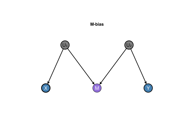
When each parent of a collider is tied to an unobserved common cause of an exposure or an outcome, the structure is often called M-bias (Pearl 2009). The five-node graph below has latents \(U_1\) and \(U_2\) and collider \(M\):

\[ X \leftarrow U_1 \rightarrow M \leftarrow U_2 \rightarrow Y. \]

\(X\) and \(Y\) are independent unconditionally. Conditioning on \(M\) opens the path through the collider and induces a spurious association. The practical warning follows at once: do not adjust for a collider (or its descendant) when estimating the effect of \(X\) on \(Y\).

Classic M-bias with explicit latents: \(X \leftarrow U_1 \rightarrow M \leftarrow U_2 \rightarrow Y\). Conditioning on the collider \(M\) opens a non-causal path between \(X\) and \(Y\) (dagplot_m_bias).

5.2.6 d-Separation: Connecting Graph Structure to Conditional Independence

d-separation is a graph-theoretic criterion that connects graph structure to conditional independence (Pearl 2009). Two nodes \(X\) and \(Y\) are d-separated by a set \(Z\) if all paths between \(X\) and \(Y\) are blocked by \(Z\).

Path blocking rules (based on the three patterns):

  • Chain: \(A \rightarrow B \rightarrow C\): Path is blocked if \(B \in Z\)
  • Fork: \(A \leftarrow B \rightarrow C\): Path is blocked if \(B \in Z\)
  • Collider: \(A \rightarrow B \leftarrow C\): Path is blocked if \(B \notin Z\) and no descendant of \(B\) is in \(Z\)

Why d-separation matters: If \(X\) and \(Y\) are d-separated by \(Z\) in the graph, then \(X ⫫ Y \mid Z\) in any probability distribution compatible with the graph structure.

5.2.7 Implementation: d-Separation Examples

We can verify d-separation properties in code:

# Find project root and include ensure_packages.jl
project_root = let
    current = pwd()
    while !isfile(joinpath(current, "Project.toml")) && !isfile(joinpath(current, "_quarto.yml"))
        parent = dirname(current)
        parent == current && break
        current = parent
    end
    current
end
include(joinpath(project_root, "scripts", "ensure_packages.jl"))
@auto_using CausalDynamics Graphs

# Example 1: Chain A → B → C
# A and C are d-separated by B (mediator blocks the path)
g_chain = SimpleDiGraph(3)
add_edge!(g_chain, 1, 2)  # A → B
add_edge!(g_chain, 2, 3)  # B → C

println("Chain pattern: A → B → C")
println("A ⫫ C | B: ", CausalDynamics.d_separated(g_chain, 1, 3, [2]))  # true: blocked by B
println("A ⫫ C: ", CausalDynamics.d_separated(g_chain, 1, 3, []))  # false: path exists when not conditioning

# Example 2: Fork A ← B → C
# A and C are d-separated by B (common cause blocks the path)
g_fork = SimpleDiGraph(3)
add_edge!(g_fork, 2, 1)  # B → A
add_edge!(g_fork, 2, 3)  # B → C

println("\nFork pattern: A ← B → C")
println("A ⫫ C | B: ", CausalDynamics.d_separated(g_fork, 1, 3, [2]))  # true: blocked by B
println("A ⫫ C: ", CausalDynamics.d_separated(g_fork, 1, 3, []))  # false: path exists when not conditioning

# Example 3: Collider A → B ← C
# A and C are independent marginally, but dependent when conditioning on B
g_collider = SimpleDiGraph(3)
add_edge!(g_collider, 1, 2)  # A → B
add_edge!(g_collider, 3, 2)  # C → B

println("\nCollider pattern: A → B ← C")
println("A ⫫ C: ", CausalDynamics.d_separated(g_collider, 1, 3, []))  # true: no path (collider blocks)
println("A ⫫ C | B: ", CausalDynamics.d_separated(g_collider, 1, 3, [2]))  # false: conditioning on collider opens path

# Example 4: More complex graph
# Z → X → Y ← W, with Z → W
# Check d-separation of X and Y given different sets
g_complex = SimpleDiGraph(4)
add_edge!(g_complex, 1, 2)  # Z → X
add_edge!(g_complex, 2, 3)  # X → Y
add_edge!(g_complex, 4, 3)  # W → Y
add_edge!(g_complex, 1, 4)  # Z → W

println("\nComplex graph: Z → X → Y ← W, Z → W")
println("X ⫫ Y: ", CausalDynamics.d_separated(g_complex, 2, 3, []))  # false: direct path X → Y
println("X ⫫ Y | W: ", CausalDynamics.d_separated(g_complex, 2, 3, [4]))  # false: still direct path
println("Z ⫫ Y | X: ", CausalDynamics.d_separated(g_complex, 1, 3, [2]))  # true: X blocks path Z → X → Y
Chain pattern: A → B → C
A ⫫ C | B: true
A ⫫ C: false

Fork pattern: A ← B → C
A ⫫ C | B: true
A ⫫ C: false

Collider pattern: A → B ← C
A ⫫ C: true
A ⫫ C | B: false

Complex graph: Z → X → Y ← W, Z → W
X ⫫ Y: false
X ⫫ Y | W: false
Z ⫫ Y | X: false

5.2.8 Sparse Matrices: The Computational Bridge

Graph theory, linear algebra, and structural equations meet in a sparse matrix. For a static linear SCM the usual compact form is (Peters et al. 2017)

\[ \mathbf{X} = B\mathbf{X} + \mathbf{U}, \]

or equivalently \(\mathbf{X} = (I - B)^{-1}\mathbf{U}\) when \(I-B\) is invertible. The convention used here (and in much of the linear-SEM literature) is

\[ B_{ij} = \text{coefficient of $X_j$ in the equation for $X_i$} \quad\Longleftrightarrow\quad \text{edge } X_j \rightarrow X_i. \]

So the support of \(B\) (where \(B_{ij}\neq 0\)) is exactly the edge set of \(G\), written as a matrix. Most entries are zero: that is sparsity as modelling assumption and as computational fact. Time-indexed linear dynamics use the same idea with a transition map \(F\) in \(\mathbf{X}_{t+1} = F\mathbf{X}_t + \cdots\) (Chapter 4).

For the linear-algebra side of this bridge, the usual reference ladder is (Strang 2016) for foundations, (Horn and Johnson 2013) for matrix analysis proper, (Golub and Van Loan 2013) for numerical matrix computations, and (Davis 2006) for sparse direct methods (the algorithmic home of compressed adjacency and factorisation).

A standard pedagogical triple is therefore:

DAG (which edges) \(\;\longleftrightarrow\;\) matrix \(B\) (which structural parameters) \(\;\longleftrightarrow\;\) structural equations (the mechanisms).

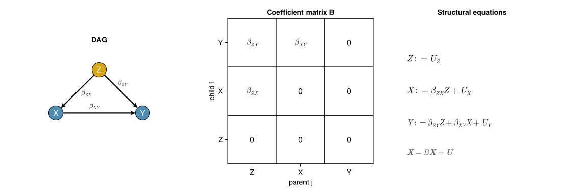
Start with the general confounding DAG \(Z\rightarrow X\rightarrow Y\), \(Z\rightarrow Y\), labelled by structural path coefficients \(\beta_{ZX}\), \(\beta_{XY}\), and \(\beta_{ZY}\) (Wright’s notation; the mediated path is the product \(\beta_{ZX}\beta_{XY}\)). The numeric example below is the same graph with concrete values filled in (Peters et al. 2017).

project_root = let
    current = pwd()
    while !isfile(joinpath(current, "Project.toml")) && !isfile(joinpath(current, "_quarto.yml"))
        parent = dirname(current)
        parent == current && break
        current = parent
    end
    current
end
include(joinpath(project_root, "scripts", "ensure_packages.jl"))
@auto_using DAGMakie CairoMakie Graphs SparseArrays StableRNGs

# Nodes: 1=Z, 2=X, 3=Y  —  Z → X → Y, Z → Y
g_conf = SimpleDiGraph(3)
add_edge!(g_conf, 1, 2)
add_edge!(g_conf, 2, 3)
add_edge!(g_conf, 1, 3)
labels_conf = ["Z", "X", "Y"]

# Graphs.edges order: 1→2, 1→3, 2→3
elabels_alg = structural_edge_labels(
    g_conf,
    ["\\beta_{ZX}", "\\beta_{ZY}", "\\beta_{XY}"];
    latex = true,
)

# Display matrix: B[i,j] on parent j → child i (zeros as "0")
B_alg_display = [
    "0"          "0"          "0";
    "\\beta_{ZX}" "0"          "0";
    "\\beta_{ZY}" "\\beta_{XY}" "0";
]

"""Draw an unshaded grid of matrix entries (numeric or TeX strings).

Non-zero / non-\"0\" entries are bold. Axis defaults match the SEM convention
B[i,j] = weight on parent j → child i.
"""
function coefficient_matrix_grid!(
    ax, B, tick_labels;
    digits = 1,
    fontsize = 18,
    xlabel = "parent j",
    ylabel = "child i",
)
    n = size(B, 1)
    for i in 1:n, j in 1:n
        poly!(ax, Rect(j - 0.5, i - 0.5, 1, 1);
            color = :white, strokecolor = :black, strokewidth = 1.25)
        entry = B[i, j]
        if entry isa Real
            text_str = string(round(entry; digits = digits))
            is_zero = iszero(entry)
            label = text_str
        else
            text_str = String(entry)
            is_zero = text_str == "0" || text_str == "0.0"
            label = occursin(r"[\\^_{}]", text_str) ? Makie.latexstring(text_str) : text_str
        end
        text!(ax, j, i;
            text = label,
            align = (:center, :center),
            color = :black,
            fontsize = fontsize,
            font = is_zero ? :regular : :bold,
        )
    end
    ax.xticks = (1:n, tick_labels)
    ax.yticks = (1:n, tick_labels)
    ax.xlabel = xlabel
    ax.ylabel = ylabel
    ax.yreversed = true
    ax.aspect = DataAspect()
    xlims!(ax, 0.5, n + 0.5)
    ylims!(ax, 0.5, n + 0.5)
    return ax
end
Main.Notebook.coefficient_matrix_grid!

General linear confounding SCM: DAG with structural path coefficients, symbolic coefficient matrix \(B\), and structural assignments. Non-zeros of \(B\) are the directed edges (\(B_{ij}\neq 0\) means \(X_j\rightarrow X_i\)) (Peters et al. 2017).

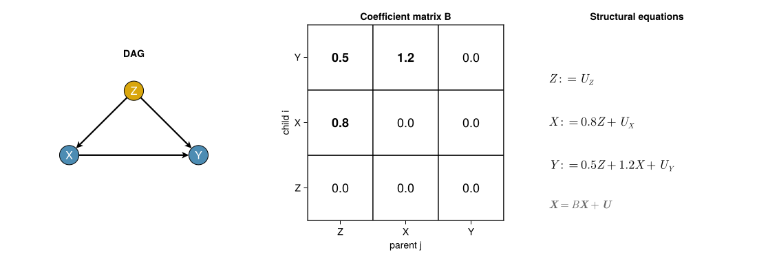
A numeric specialisation of the same graph replaces each \(\beta\) by a concrete weight.

# B[i,j] = coeff of X_j in equation for X_i  (edge j → i)
B_conf = [
    0.0  0.0  0.0;   # Z := U_Z
    0.8  0.0  0.0;   # X := 0.8 Z + U_X
    0.5  1.2  0.0;   # Y := 0.5 Z + 1.2 X + U_Y
]
3×3 Matrix{Float64}:
 0.0  0.0  0.0
 0.8  0.0  0.0
 0.5  1.2  0.0

Numeric instance of the confounding SCM: the same DAG–matrix–equation triple with \(\beta_{ZX}=0.8\), \(\beta_{ZY}=0.5\), and \(\beta_{XY}=1.2\).

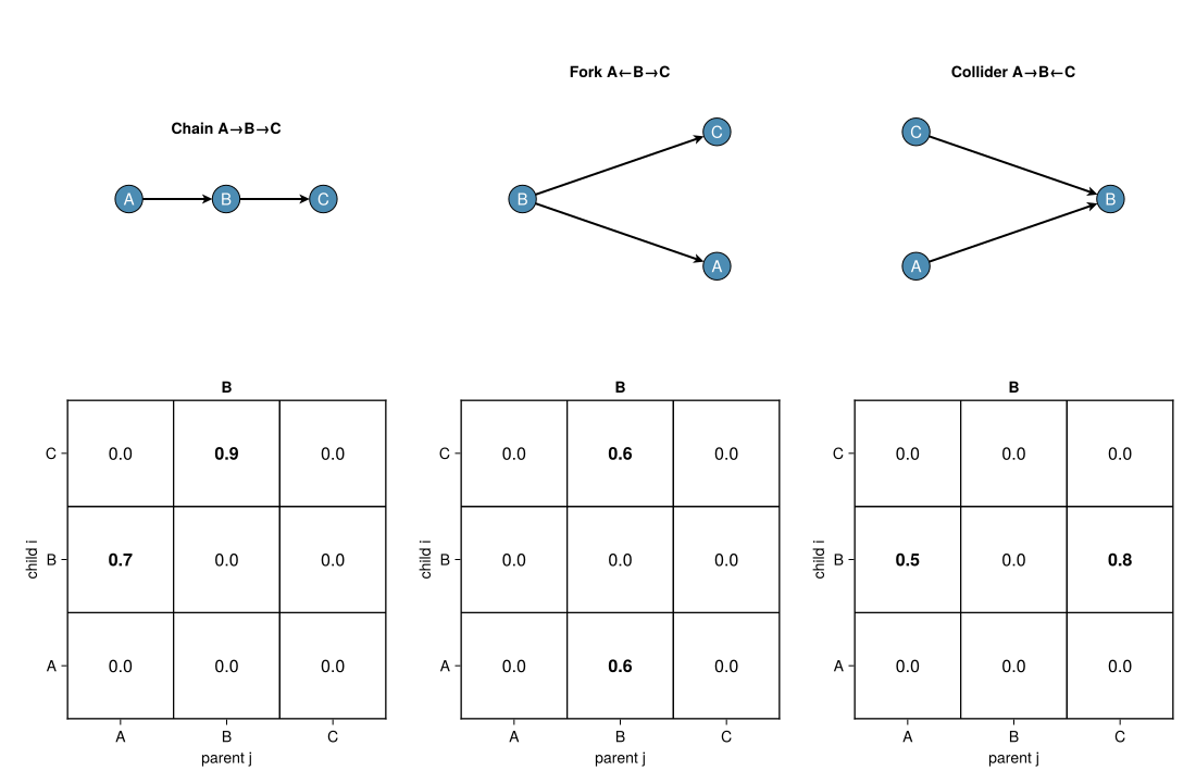
The three fundamental patterns from earlier in the chapter have the same bridge: each missing edge is a structural zero in \(B\).

# Chain / fork / collider on labels A,B,C (nodes 1,2,3)
g_ch = SimpleDiGraph(3); add_edge!(g_ch, 1, 2); add_edge!(g_ch, 2, 3)
B_ch = [0.0 0.0 0.0; 0.7 0.0 0.0; 0.0 0.9 0.0]   # A→B→C

g_fk = SimpleDiGraph(3); add_edge!(g_fk, 2, 1); add_edge!(g_fk, 2, 3)
B_fk = [0.0 0.6 0.0; 0.0 0.0 0.0; 0.0 0.6 0.0]   # A←B→C

g_co = SimpleDiGraph(3); add_edge!(g_co, 1, 2); add_edge!(g_co, 3, 2)
B_co = [0.0 0.0 0.0; 0.5 0.0 0.8; 0.0 0.0 0.0]   # A→B←C

pattern_pack = (
    ("Chain A→B→C", g_ch, B_ch, ["A", "B", "C"]),
    ("Fork A←B→C", g_fk, B_fk, ["A", "B", "C"]),
    ("Collider A→B←C", g_co, B_co, ["A", "B", "C"]),
)
(("Chain A→B→C", SimpleDiGraph{Int64}(2, [[2], [3], Int64[]], [Int64[], [1], [2]]), [0.0 0.0 0.0; 0.7 0.0 0.0; 0.0 0.9 0.0], ["A", "B", "C"]), ("Fork A←B→C", SimpleDiGraph{Int64}(2, [Int64[], [1, 3], Int64[]], [[2], Int64[], [2]]), [0.0 0.6 0.0; 0.0 0.0 0.0; 0.0 0.6 0.0], ["A", "B", "C"]), ("Collider A→B←C", SimpleDiGraph{Int64}(2, [[2], Int64[], [2]], [Int64[], [1, 3], Int64[]]), [0.0 0.0 0.0; 0.5 0.0 0.8; 0.0 0.0 0.0], ["A", "B", "C"]))

The three fundamental patterns as DAG–matrix pairs. Zeros of \(B\) are forbidden edges; non-zeros are the dyads that define the pattern.

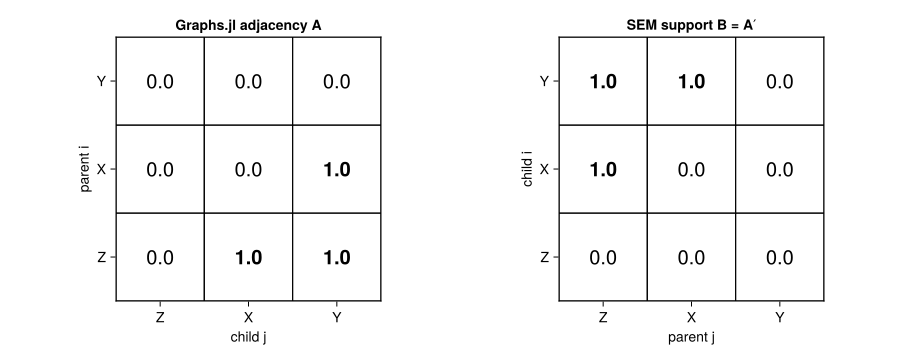
The same confounding graph makes the index convention concrete: Graphs.jl stores edges as \(A_{ij}=1\) for \(i\rightarrow j\), while the SEM matrix stores \(B_{ji}\neq 0\) for that edge. Visually, the support of \(B\) is the transpose of \(A\) (when edge weights are set to one).

A_conf = Float64.(Matrix(adjacency_matrix(g_conf)))
# Unit-weight SEM matrix: B_unit[i,j] = 1 iff edge j → i
B_unit = Matrix(transpose(A_conf))
3×3 Matrix{Float64}:
 0.0  0.0  0.0
 1.0  0.0  0.0
 1.0  1.0  0.0

Index convention: Graphs.jl adjacency \(A\) (\(A_{ij}=1\) means \(i\rightarrow j\)) versus unit-weight SEM matrix \(B=A^\top\) (\(B_{ij}=1\) means \(j\rightarrow i\)). Weighted \(B\) in the confounding figure is this support with coefficients filled in.

5.2.9 Implementation: adjacency sparsity at scale

Graphs.adjacency_matrix uses the opposite index convention for the binary edge indicator (\(A_{ij}=1\) means edge \(i\rightarrow j\)). The support still matches \(B^\top\) for a linear SEM written as above. Sparse storage matters once \(n\) is large and \(|E|\ll n^2\).

project_root = let
    current = pwd()
    while !isfile(joinpath(current, "Project.toml")) && !isfile(joinpath(current, "_quarto.yml"))
        parent = dirname(current)
        parent == current && break
        current = parent
    end
    current
end
include(joinpath(project_root, "scripts", "ensure_packages.jl"))
@auto_using Graphs SparseArrays StableRNGs

# Same confounding topology as the figure (nodes Z,X,Y)
g = SimpleDiGraph(3)
add_edge!(g, 1, 2)
add_edge!(g, 2, 3)
add_edge!(g, 1, 3)
A = adjacency_matrix(g)
println("Graphs.jl adjacency A (A[i,j]=1 ⇒ i→j):")
println(Matrix(A))
println("SEM coefficient support is A': non-zeros mark parents in each equation.")
println("nnz(A) = ", nnz(sparse(A)), " of ", length(A))

rng = StableRNG(3)
g_large = SimpleDiGraph(100)
while ne(g_large) < 200
    s = rand(rng, 1:100)
    d = rand(rng, 1:100)
    if s != d
        add_edge!(g_large, s, d)
    end
end
A_large = adjacency_matrix(g_large)
println("\n100-node draw with ", ne(g_large), " edges:")
println("  dense Float64 footprint (approx): ", 100 * 100 * sizeof(Float64), " bytes")
println("  sparse nnz: ", nnz(sparse(A_large)))
Graphs.jl adjacency A (A[i,j]=1 ⇒ i→j):
[0 1 1; 0 0 1; 0 0 0]
SEM coefficient support is A': non-zeros mark parents in each equation.
nnz(A) = 3 of 9

100-node draw with 200 edges:
  dense Float64 footprint (approx): 80000 bytes
  sparse nnz: 200

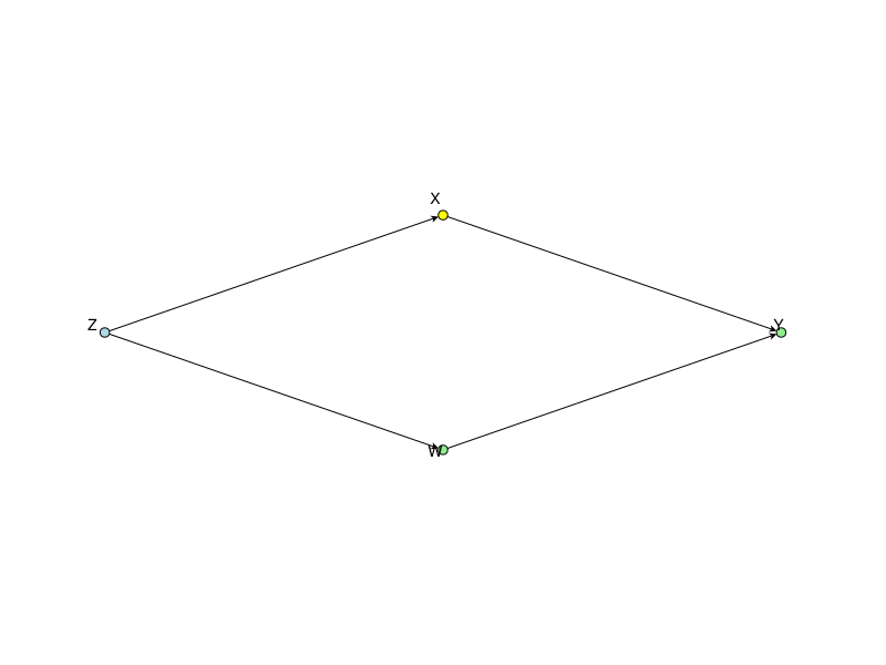
5.2.10 Markov Boundary: The Minimal Sufficient Set

The Markov boundary of a node \(X\) is the minimal set of nodes that makes \(X\) conditionally independent of all other nodes (Pearl 2009). It consists of:

  1. Parents of \(X\): Direct causes
  2. Children of \(X\): Direct effects
  3. Other parents of children: Spouses (other direct causes of \(X\)’s children)

The Markov boundary provides a principled criterion for determining the minimal set of variables needed for causal reasoning about \(X\).

5.2.11 Implementation: Computing Markov Boundary

We can compute the Markov boundary using graph structure. The Markov boundary of a node consists of its parents, children, and other parents of children (spouses):

# Find project root and include ensure_packages.jl
project_root = let
    current = pwd()
    while !isfile(joinpath(current, "Project.toml")) && !isfile(joinpath(current, "_quarto.yml"))
        parent = dirname(current)
        parent == current && break
        current = parent
    end
    current
end
include(joinpath(project_root, "scripts", "ensure_packages.jl"))
@auto_using DAGMakie CairoMakie Graphs

# Example graph: Z → X → Y ← W, with Z → W
# For node X, Markov boundary should include:
# - Parents: Z
# - Children: Y
# - Spouses: W (other parent of Y)
g = SimpleDiGraph(4)
add_edge!(g, 1, 2)  # Z → X
add_edge!(g, 2, 3)  # X → Y
add_edge!(g, 4, 3)  # W → Y
add_edge!(g, 1, 4)  # Z → W

function markov_boundary(g::AbstractGraph, node::Integer)
    """
    Compute the Markov boundary of a node in a directed graph.

    The Markov boundary consists of:

    - Parents: nodes with edges into the node
    - Children: nodes with edges from the node
    - Spouses: other parents of the node's children
    """


    # Parents: nodes with edges into node
    parents = Vector{Int}()
    for src in 1:nv(g)
        if has_edge(g, src, node)
            push!(parents, src)
        end
    end

    # Children: nodes with edges from node
    children = Vector{Int}()
    for dst in 1:nv(g)
        if has_edge(g, node, dst)
            push!(children, dst)
        end
    end

    # Spouses: other parents of children
    spouses = Set{Int}()
    for child in children
        for parent in 1:nv(g)
            if has_edge(g, parent, child) && parent != node
                push!(spouses, parent)
            end
        end
    end

    return (parents=parents, children=children, spouses=collect(spouses),
            boundary=sort(unique([parents; children; collect(spouses)])))
end

# Compute Markov boundary for X (node 2)
mb = markov_boundary(g, 2)
println("Markov boundary for X (node 2):")
println("  Parents: ", mb.parents)  # [1] = Z
println("  Children: ", mb.children)  # [3] = Y
println("  Spouses: ", mb.spouses)  # [4] = W
println("  Full boundary: ", mb.boundary)  # [1, 3, 4] = Z, Y, W

# Visualise graph with Markov boundary highlighted
let
    node_colors = [
        RGBf(0.85, 0.65, 0.05),  # Z (parent)
        RGBf(0.20, 0.55, 0.45),  # X (Markov boundary focus)
        RGBf(0.30, 0.55, 0.70),
        RGBf(0.30, 0.55, 0.70),
    ]
    fig, ax, p = dagplot(g;
        figure_size = (800, 600),
        layout_mode = :acyclic,
        node_color = node_colors,
        nlabels = ["Z", "X", "Y", "W"],
        node_size = 40,
        edge_width = 2.0,
        arrow_size = 15,
        nlabels_fontsize = 16,
        nlabels_color = :white,
        nlabels_align = (:center, :center),
        nlabels_distance = 0,
        auto_align_labels = false,
        padding = 0.40,
    )
    fig  # Only this gets displayed
end
Markov boundary for X (node 2):
  Parents: [1]
  Children: [3]
  Spouses: [4]
  Full boundary: [1, 3, 4]

Computing Markov boundary for causal reasoning

5.3 Stratum context

This chapter addresses Seeing in the Structural layer: what can we infer about causal structure from conditional independences and graph properties? Graph theory provides the mathematical foundation for representing and reasoning about structure. Many concepts here are abstract and not tied to a particular time index:

  • Graph structure: assumed causal structure
  • d-separation: implied conditional independences
  • Sparse matrices: computational structure induced by sparse dependencies
  • Markov boundary: minimal sufficient sets for prediction/adjustment

All complex structures are built from combinations of dyads, and graph theory provides the language for understanding these structures.

5.4 Summary

Graph theory supplies the language for Seeing in the Structural layer: dyads compose into chains, forks, and colliders; d-separation links those patterns to conditional independence; M-bias shows how conditioning on a collider can invent dependence; sparse coefficient matrices \(B\) carry the same edge set into linear algebra; and the Markov boundary names a minimal sufficient set for local reasoning about a node.

5.5 Further Reading

  • Pearl (2009): Causality: Graph theory and d-separation
  • Spirtes et al. (2000): Causation, Prediction, and Search: Graph-theoretic causal discovery
  • Chernozhukov et al. (2024): Applied Causal Inference Powered by ML and AI, Chapters 6–7 and 11 (SEMs to DAGs, d-separation and backdoor, good and bad controls)
  • Strang (2016): Introduction to Linear Algebra: Foundations for reading graphs as matrices (course site)
  • Horn and Johnson (2013): Matrix Analysis: The standard analytic reference for eigenvalues, norms, and canonical forms (DOI)
  • Golub and Van Loan (2013): Matrix Computations: The numerical linear-algebra bible (DOI)
  • Davis (2006): Direct Methods for Sparse Linear Systems: Sparse storage, ordering, and factorisation (DOI)
  • Structural Causal Models as Executable Mechanisms: How graphs are encoded in SCMs